
6 - MSC
SDL-RT integrates the Message Sequence Chart dynamic view. On such a diagram, time flows from top to bottom. Lifelines represent SDL-RT agents or semaphores and key SDL-RT events are represented. The diagram put up front the sequence in which the events occur.
In the case of embedded C++ it is possible to use a lifeline to represent an object. In that case the type is object and the name should be <object name>:<class name>
6.1 - Agent instance
An agent instance starts with an agent instance head followed by an instance axis and ends with an instance tail or an instance stop as shown in the diagrams below.
The type of the agent can be specified on top of the head symbol and the name of the agent is written in the instance head symbol. The instance tail symbol means the agent lives after the diagram. The instance stop symbol means the agent no longer exist after the symbol.
When an agent creates another agent a dashed arrow goes from the parent agent to the child agent.
Example:
6.2 - Semaphore representation
A semaphore representation is made of a semaphore head, a lifeline, and a semaphore end or tail. The symbols are the same as for a process except for the head of the semaphore.
6.3 - Semaphore manipulations
Several cases are to be considered with semaphore manipulations. A process makes an attempt to take a semaphore, its attempt can be successful or unsuccessful, if successful the semaphore might still be available (counting semaphore) or become unavailable. During the time the semaphore is unavailable, its lifeline gets thicker until it is released.
The manipulation symbols are the following:
Example:
6.4 - Message exchange
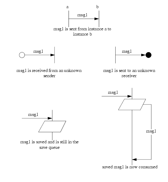
A message symbol is a simple arrow with its name and optional parameters next to it. The arrow can be horizontal meaning the message arrived instantly to the receiver or the arrow can go down to show the message arrived after a certain time or after another event. A message can not go up !
When the sender and the receiver are represented on the diagram the arrow is connected to their instances. If the sender is missing it is replaced by a white circle, if the receiver is missing it is replaced by a black circle.The name of the sender or the receiver can optionally be written next to the circle.
A message is considered received by an agent when it is read from the agent's message queue; not when it arrives in the message queue !
6.5 - Synchronous calls
This representation is used when using embedded C++ to show method calls on an object. Object can be represented by lifelines. Synchronous calls are shown with an arrow to the instance representing the object. While the object has the focus its lifeline becomes a black rectangle and the agent lifeline becomes a white rectangle. That means the execution flow has been transferred to the object. When the method returns a dashed arrow return to the method caller.
6.6 - State
A lifeline represents a process and depending on its internal state a process reacts differently to the same message. It is interesting to represent a process state on its lifeline. It is also interesting to represent a global state for information. In that case the state symbol covers the concerned instances. In both cases the same symbol is used.
Example:
6.7 - Timers
Two symbols are available for each timer action depending if the beginning and the end of the timer are connected or not. The timer name is by the cross and timeout value is optional. When specified the timeout value unit is not specified; it is usually RTOS tick counts.
Examples:
6.8 - Time interval
To specify a time interval between two events the following symbol is used.
Time constraint syntax is the following:
Note it is possible to use time constraint on a single MSC reference.
- absolute time is expressed with an @ up front the time value,
- relative time is expressed with nothing up front its value,
- time interval is expressed between square brackets,
- time unit is RTOS specific -usually tick counts- unless specified (s, ms, Ás).
Absolute time can also be specified with the following symbol:
Examples:
Table 1: Examples of time constraint expressions Expression Meaning 1.3ms takes 1.3 ms to do
6.9 - Coregion
Coregion is used whenever the sequence of events does not matter. Events in a coregion can happen in any order. The coregion symbol replaces the lifeline instance.
Example:
6.10 - MSC reference
MSC reference allows to refer to another MSC. The resulting MSC is smaller and more legible.
A reference concerns the connected instances. An instance is connected if its lifeline disappears in the symbol. An instance is not connected if it goes over the reference symbol.
Example:
6.11 - Inline expressions
Inline expressions allow to add semantics to the MSC diagrams. An inline expression is a box spanning one or more instances, and that can have one or several compartments: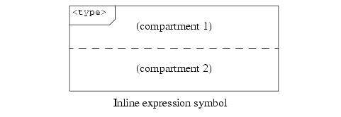
An inline expression can specify:
An instance not concerned by an inline expression will appear to go behind it. Inline expression can be nested.
- That the sequence of events it contains is optional (inline expression type opt);
- That its compartments are mutually exclusive: one and exactly one of them must happen, but not several (inline expression type alt);
- That the events in all its compartments happen in parallel (inline expression type par);
- That the events within it may happen one or several times, without optional minimum and maximum numbers of repeats (inline expression type loop);
- That the events within it may happen in any order across the instances, while still being ordered as displayed on a single instance (inline expression type seq);
- That the events within it generate an exception, ending the scenario described by the MSC (inline expression type exc).
Example: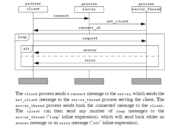
6.12 - Text symbol
The text symbol contains data or variable declarations if needed in the MSC.
6.13 - Comment
As its name states...
6.14 - Action
An action symbol contains a set of instructions in C code. The syntax is the one of C language.
Examples:
6.15 - Property Sequence Charts (PSC)
SDL-RT integrates the concept of Property Sequence Chart, allowing to create diagrams very similar to MSC diagrams specifying properties that must be matched by an execution trace. PSC diagrams are represented in the same way as MSC diagrams, with a few additional concepts, that are described in the following paragraphs.
6.15.1 Component instance
A component instance in a PSC diagram has the same semantics as an agent instance in a MSC diagram and is represented the same way, as described in "Agent instance" on pageá41.
6.15.2 Normal, required and fail messages
A normal message is a message that is part of the necessary events for the property to be checked. They are part of the 'cause' part of the PSC. If any of these are not matched, the property doesn't apply and shouldn't be checked. Required and failed messages are part of the 'consequence' part of the PSC. The first one is a message that must occur, and the second one is a message that must not occur.
Normal, required and fail messages are represented the same way as messages in a MSC as described in "Message exchange" on pageá44. However, the text for the message has an additional prefix, which is 'e:' for normal messages, 'r:' for required ones and 'f:' for fail ones.
6.15.3 Parallel, alternative and loop operator
These operators in PSC diagrams have the same semantics and representation as the corresponding inline expressions in a MSC diagram, as described in "Inline expressions" on pageá56.
6.15.4 Strict operator
In a PSC diagram, the ordering of the message sends and receives is by default a loose one: the order shown in the PSC must be the one in the trace, but any event can occur in between in the trace. The strict operator allows to specify that two events must be found one after the other, with no other event happening in between. It is represented with a thick line on the instance on which the events occur: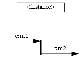
The receiving of the normal message m1 has to be directly followed by the sending of the required message m2, or the property won't match. Without the strict operator, m2 could have been sent after any number of events on the instance.
6.15.5 Relative time constraint
Relative time constraints have the same semantics and representation as time intervals in MSC diagrams, as described in "Time interval" on pageá51.
6.15.6 Unwanted/wanted message or chain constraints
PSC diagrams allow to specify constraints on message, giving a condition for them to be matched. These constraints can be of 3 kinds:
A constraint is specified via a symbol, displayed either near the sending of the message for a constraint to match before the message, or near its receiving for a constraint to be matched after the message. A text describing the messages in the constraint appear under the symbol. Each message in this text is written with a specific syntax:
- Unwanted message constraints specify a list of messages that must not occur before or after the message to be matched. If any of the messages in the list happens, the property does not match.
- Unwanted chain constraints specify a sequence of messages that must not occur as a whole in the specified order, before or after the message to be matched. If the whole sequence appears, then the property does not match.
- Wanted chain constraints specify a sequence of messages that must occur as a whole in the specified order, before or after the message to be matched. If the whole sequence does not appears, then the property does not match.
<sender instance name>.<message name>.<receiver instance name>
The text can also just be a label, with the actual constraint given in a text box associated to the label: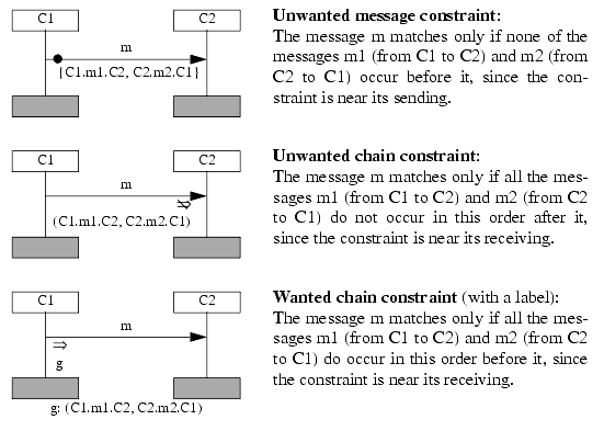
SDL-RT MSC/PSC diagrams actually introduce a more general unwanted constraint, called an alternative chain constraint, that combines the features of the unwanted message constraint and of the unwanted chain constraint: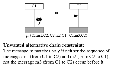
Note that the syntax is compatible with unwanted chain constraint: as long a no | character is present in the constraint text, the unwanted alternative chain constraint is the same as the unwanted chain constraint with the same text.
SDL-RT PSC diagrams also allow to specify constraints between square brackets before or after the message text. The symbols are then given in a textual form. For example: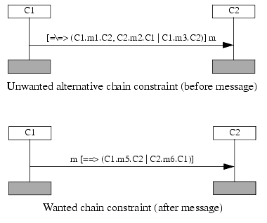
Note that unwanted message constraints cannot be represented textually. However, they might be specified with the equivalent unwanted alternative chain constraint:
6.16 - High-level MSC (HMSC)
High level MSC diagram is a synthetic view of how MSCs relate to each other. It is only a few symbols: start, stop, alternative, parallel, state or condition, and MSC reference.
The SDL-RT HMSC starts with the start symbol and ends with the stop symbol. The parallel symbol means the following connected path will be executed in parallel. The Alternative symbol means one and only one of the connected path is executed. Whenever two paths meet again the path separator symbol is to be repeated. That means if a parallel symbol is used that creates two different paths, the parallel symbol should be used when the path merge back.
Symbols are connected with lines or arrows if clearer. A symbol is entered by its upper level edge and leaved by any other edge.
Example:
 http://www.sdl-rt.org info@sdl-rt.org |