11 - Textual representation
The storage format for SDL-RT diagrams follows the XML (eXtensible Markup Language standard from W3C available at http://www.w3.org) standard. The MSC diagram being quite different from the other diagrams, there are two different document type definitions: one for MSCs, and one for all other diagrams.
11.1 - Standard diagram DTD
11.1.1 Principles
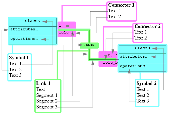
The file describes the whole diagram in terms of symbols, links and connectors. A link is subdivided into link segments. Each of these elements have one or several texts.
Here is an example of this organization with a UML class diagram:
11.1.2 DTD text
<!-- Entity for booleans -->
<!-- =================== -->
<!ENTITY % boolean "(TRUE|FALSE)">
<!-- Entities for symbol types -->
<!-- ========================= -->
<!ENTITY % sdlSymbolTypes1 "sdlSysDgmFrm|sdlSysTypeDgmFrm|sdlBlkDgmFrm|sdlBlkTypeDgmFrm|sdlBlkType|sdlBlk|sdlBlkTypeInst|sdlPrcsType|sdlPrcs|sdlPrcsTypeInst">
<!ENTITY % sdlSymbolTypes2 "sdlInherits|sdlPrcsTypeDgmFrm|sdlPrcsDgmFrm|sdlPrcdDgmFrm|sdlStart|sdlState|sdlInputSig|sdlSendSig|sdlSaveSig|sdlContSig">
<!ENTITY % sdlSymbolTypes3 "sdlTask|sdlDecision|sdlTransOpt|sdlJoin|sdlText|sdlComment|sdlTextExt|sdlCnctrOut|sdlCnctrIn|sdlPrcsCreation|sdlStop|sdlObjCre">
<!ENTITY % sdlSymbolTypes4 "sdlInitTimer|sdlResetTimer|sdlSemDecl|sdlSemTake|sdlSemGive|sdlPrcdProto|sdlPrcdDecl|sdlPrcdCall|sdlPrcdStart|sdlPrcdReturn">
<!ENTITY % sdlSymbolTypes5 "sdlCompState|sdlCompStateDef|sdlService|sdlCompStateDgmFrm|sdlServDgmFrm">
<!ENTITY % sdlSymbolTypes "%sdlSymbolTypes1;|%sdlSymbolTypes2;|%sdlSymbolTypes3;|%sdlSymbolTypes4;|%sdlSymbolTypes5;">
<!ENTITY % hmscSymbolTypes "hmscDgmFrm|hmscParallel|hmscStart|hmscEnd|hmscCondition|hmscMscRef|hmscAlternativePoint">
<!ENTITY % mscdocSymbolTypes "mscdocDgmFrm|mscdocMscRef|mscdocHeader">
<!ENTITY % umlClassSymbolTypes "umlClassDgmFrm|umlPckg|umlClass|umlComment|umlSys|umlBlkCls|umlBlk|umlPrcsCls|umlPrcs">
<!ENTITY % umlDeplSymbolTypes "umlDeplDgmFrm|umlNode|umlComp|umlFile">
<!ENTITY % umlUCSymbolTypes "umlUCDgmFrm|umlUseCase|umlActor">
<!ENTITY % SymbolType "(%sdlSymbolTypes;|%hmscSymbolTypes;|%mscdocSymbolTypes;|%umlClassSymbolTypes;|%umlDeplSymbolTypes;|%umlUCSymbolTypes;)">
<!-- Entity for connector types -->
<!-- ========================== -->
<!ENTITY % ConnectorType "(void|chnl|chnlgate|sdlarrow|hmscarrow|umlcvoid|umlassoc|umlrole|umldvoid)">
<!-- Entity for side for connectors -->
<!-- ============================== -->
<!ENTITY % Side "(n|s|w|e|x|y)">
<!-- Entity for end types for connectors -->
<!-- =================================== -->
<!ENTITY % ConnectorEndType "(voidend|arrow|midarrow|fullarrow|outltri|outldiam|filldiam|outldiamarw|filldiamarw)">
<!-- Entity for link segment orientation -->
<!-- =================================== -->
<!ENTITY % Orientation "(h|v)">
<!-- Entity for link types -->
<!-- ===================== -->
<!ENTITY % LinkType "(sbvoid|dbvoid|ssvoid|dsvoid|chnl|dec|transopt|assoc|spec|aggr|comp|cnx|dep)">
<!-- Entity for diagram types -->
<!-- ======================== -->
<!ENTITY % DiagramType "(sys|systype|blk|blktype|prcs|prcstype|prcd|hmsc|mscdoc|class|usec|depl|compstate|service)">
<!-- Element for text in symbols/links/... -->
<!-- ===================================== -->
<!ELEMENT Text (#PCDATA)>
<!ATTLIST Text
id CDATA "0"
>
<!-- Element for symbols -->
<!-- =================== -->
<!-- The "Symbol*" component is for symbols contained in a container symbol -->
<!ELEMENT Symbol (Text+, Symbol*)>
<!ATTLIST Symbol
symbolId ID #REQUIRED
type %SymbolType; #REQUIRED
xCenter CDATA #REQUIRED
yCenter CDATA #REQUIRED
fixedDimensions %boolean; "FALSE"
width CDATA "10"
height CDATA "10"
color CDATA "#000000"
fillColor CDATA "#ffffff"
>
<!-- Element for connectors -->
<!-- ====================== -->
<!ELEMENT Connector (Text, Text)>
<!ATTLIST Connector
connectorId CDATA ""
attachedSymbolId IDREF #REQUIRED
type %ConnectorType; #REQUIRED
isOutside %boolean; #REQUIRED
side %Side; #REQUIRED
position CDATA #REQUIRED
endType %ConnectorEndType; #REQUIRED
>
<!-- Element for link segments -->
<!-- ========================= -->
<!ELEMENT LinkSegment EMPTY>
<!ATTLIST LinkSegment
orientation %Orientation; #REQUIRED
length CDATA #REQUIRED
>
<!-- Element for links -->
<!-- ================= -->
<!ELEMENT Link (Text, Connector, Connector, LinkSegment*)>
<!ATTLIST Link
linkId CDATA ""
type %LinkType; #REQUIRED
textSegmentNum CDATA #REQUIRED
color CDATA "#000000"
reverseRead %boolean; "FALSE"
>
<!-- Element PageSpecification -->
<!-- ========================= -->
<!-- Attributes for diagram pages; all dimensions are centimetres -->
<!ELEMENT PageSpecification EMPTY>
<!ATTLIST PageSpecification
pageWidth CDATA "21"
pageHeight CDATA "29.7"
topMargin CDATA "1.5"
bottomMargin CDATA "1.5"
leftMargin CDATA "1.5"
rightMargin CDATA "1.5"
pageFooter %boolean; "TRUE"
>
<!-- Element DiagramPartition -->
<!-- ======================== -->
<!-- A partition in a diagram -->
<!ELEMENT DiagramPartition (PageSpecification, Symbol, Link*)>
<!ATTLIST DiagramPartition
name CDATA ""
nbPagesH CDATA "1"
nbPagesV CDATA "1"
>
<!-- Element for diagrams -->
<!-- ==================== -->
<!ELEMENT Diagram (DiagramPartition+)>
<!ATTLIST Diagram
type %DiagramType; #REQUIRED
name CDATA ""
cellWidthMm CDATA "5"
linksCrossingAllowed %boolean; "FALSE"
>
11.1.3 Explanations
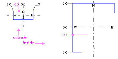
The main XML element is <Diagram>. It is split in several partitions, each being a rectangular set of pages having the same page size and margins within a partition (XML element <PageSpecification>). A partition always has an external frame, which is a symbol, containing all the symbols in it. Attributes for a symbol are all the required information to display it. In addition to its display attributes, a link also knows the index of the segment bearing its text (textSegmentNum) and a special indicator for association links giving the reading order of the association (reverseRead). The position for connectors is given by the side of the symbol to which they attach, the relative position along the symbol's border and a boolean saying if the connector is outside the symbol (normal case) or inside it (links connecting to a frame border):
A connector also has an endType specifying the symbol that appears at the link end, which may vary for a given connector type (e.g connectors for association links may end with a filled or outlined diamond to indication the association is actually a composition or aggregation).
11.2 - MSC diagram DTD
11.2.1 Principles
A MSC diagram is described mainly as a series of events happening on lifelines (instances). More precisely, it has 3 main parts:
- The first part gives the sequence of lifelines in the diagram, ordered as they should be displayed. All lifelines are listed, including collapsed ones.
- The second part lists the collapsed lifelines and the lifelines they "contain".
- The third part gives the events actually happening in the diagram. Each event has a type and a set of attributes connecting it to lifelines or other events, or giving information about how it should be displayed.
11.2.2 DTD text
<!ENTITY % MscEventType1 "MESSAGE_SEND|MESSAGE_RECEIVE|MESSAGE_SAVE|OPERATION_CALL|OPERATION_RETURN">
<!ENTITY % MscEventType2 "TIMER_START|TIMER_CANCEL|TIMER_TIMEOUT|TIME_CONSTRAINT_START|TIME_CONSTRAINT_END">
<!ENTITY % MscEventType3 "PROCESS_CREATION|PROCESS_START|PROCESS_END">
<!ENTITY % MscEventType4 "SEMAPHORE_CREATION|SEMAPHORE_START|SEMAPHORE_END|SEMAPHORE_DELETION">
<!ENTITY % MscEventType5 "SEMAPHORE_TAKE|SEMAPHORE_TAKE_SUCCEEDED|SEMAPHORE_TAKE_TIMEOUT|SEMAPHORE_GIVE">
<!ENTITY % MscEventType6 "SEGMENT_START|SEGMENT_END|ACTION_SYMBOL_START|ACTION_SYMBOL_SPACER|ACTION_SYMBOL_END">
<!ENTITY % MscEventType7 "MSC_REFERENCE_START|MSC_REFERENCE_END|INLINE_EXPRESSION_START|INLINE_EXPRESSION_SEP|INLINE_EXPRESSION_END|CONDITION_START|CONDITION_END">
<!ENTITY % MscEventType8 "TEXT_SYMBOL|UNATTACHED_COMMENT|ATTACHED_COMMENT|ABSOLUTE_TIME">
<!ENTITY % MscEventType "(%MscEventType1;|%MscEventType2;|%MscEventType3;|%MscEventType4;|%MscEventType5;|%MscEventType6;|%MscEventType7;|%MscEventType8;)">
<!ELEMENT MscDiagram (LifelineOrdering, CollapsedLifeline*, MscEventRow*)>
<!ELEMENT LifelineOrdering EMPTY>
<!ATTLIST LifelineOrdering identifiers CDATA "">
<!ELEMENT CollapsedLifeline EMPTY>
<!ATTLIST CollapsedLifeline
identifier CDATA #REQUIRED
collapsed_lifelines_ids CDATA #REQUIRED
>
<!ELEMENT MscEventRow (MscEvent+)>
<!ELEMENT MscEvent EMPTY>
<!ATTLIST MscEvent
event_type %MscEventType; #REQUIRED
lifeline_ids CDATA ""
color CDATA "#000000"
background CDATA "#ffffff"
identifier CDATA ""
type CDATA ""
text CDATA ""
text_size CDATA ""
>
11.2.3 Explanations
The main XML element is <MscDiagram>.
The first part in the diagram is given in the <LifelineOrdering> XML element: its identifiers attribute contains a space-separated list of lifeline identifiers.
The second part is given in the <CollapsedLifeline> XML elements, each associating an identifier for the collapsed lifeline to the space-separated list of identifiers for lifelines they contain (collapsed_lifelines_ids).
The third part is the sequence of <MscEvent> XML elements. Each of these elements is a description of an event happening in the diagram. The attributes for an event are:
All attributes do not apply to all event types, and may not contain the same inforamtion. Here is the compatibility matrix:
- event_type: type for the event.
- lifeline_ids: space-separated list of identifiers for lifelines involved in the event.
- color: text and outline color for the event.
- background: background color for the event if applicable.
- identifier: identifier for the event itself if one is needed. This identifier is used to link 2 related events, such as a couple MESSAGE_SEND / MESSAGE_RECEIVE or a couple TIME_CONSTRAINT_START / TIME_CONSTRAINT_END.
- type: type for object described by the event.
- text: text for the object described by the event if any.
- text_size: size for the text for the object described by the event, giving its width and its height, separated by a space, both of which can be a '-' if it's missing or not significant.
Table 2: Event attributes Event type lifeline_ids color identifier type text text_size
1. Only one lifeline identifier is allowed, which is the one on which the event happens.
2. Two lifelines must be specified. The first is the one onto which the event happens (called one, created one, etc...); the second one is the causing the action (caller, creator, etc...).
3. Several lifelines can be specified, listing all those spanned by the symbol.
4. The type is the type for the segment: suspended, method, co-region, etc...
5. The type is the type for the inline expression: opt, alt, par, etc...
6. The text size only specifies the width for the text, allowing to size the lifeline head correctly.
7. The text size allows to give the proper dimensions to the tag border in the inline expression.
 http://www.sdl-rt.org info@sdl-rt.org |